01 / University of Toronto Supermileage
UTSM dynamometer
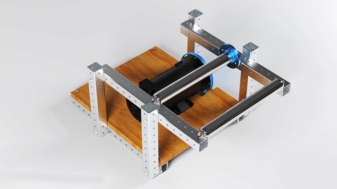
I worked with the UTSM team to redesign a dynamometer frame after excessive wobble and deformation.
01 / Project brief
Redesigning a flexible frame.
The existing dynamometer frame showed pronounced wobble and deformation during competition use.
I focused on the load path through the roller supports, frame members and corner connections.
02 / My contribution
Members, joints & load path.
I worked on material changes and corner brackets/bracing for the frame supporting the rollers and measurement motor. I treated the members and connections together, using static load calculations and ANSYS analysis to guide the redesign.
Drivetrain views
02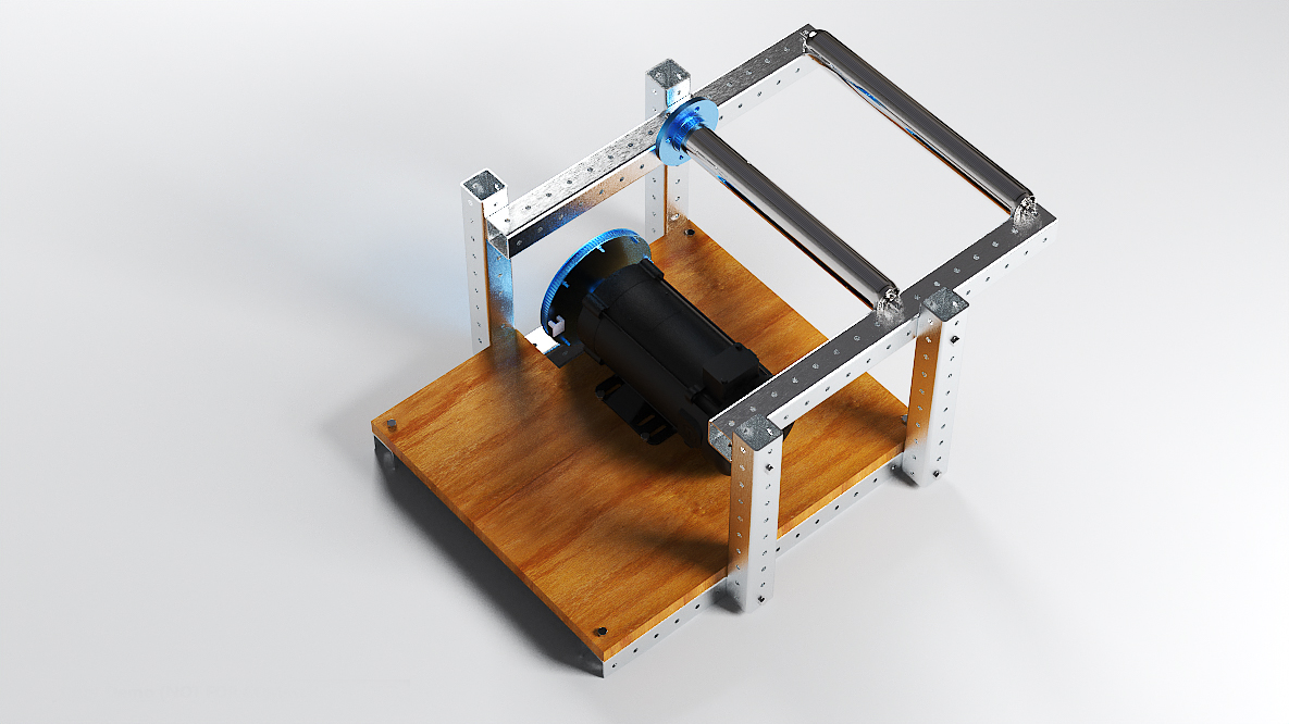
Motor and drive assembly from the drive side.
View original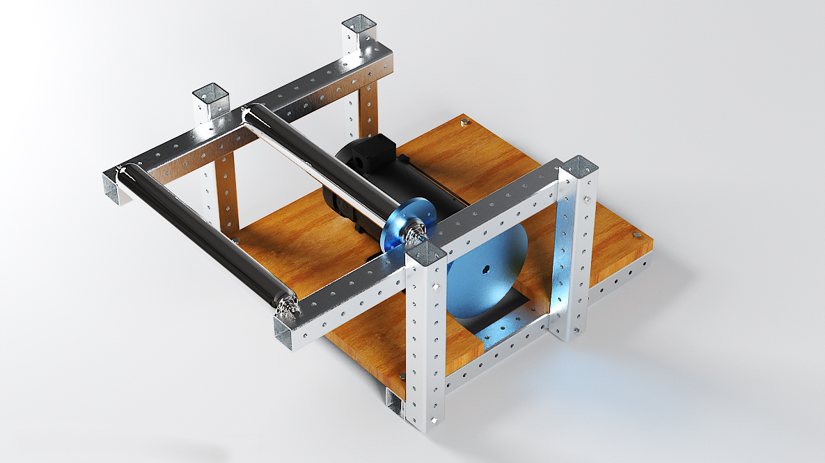
Alternate drivetrain view showing the blue geared components.
View original03 / Load model & assumptions
Start with an explicit idealization.
To examine vertical bending, I idealized each roller-support rod as a simply supported beam with a central load, assuming equal sharing between the two rods.
- Nominal design case
- 640 N
- Overload design case
- 1000 N
For the rod calculation, I split the wheel-supported vertical load Ww equally between the two rods: P = Ww/2.
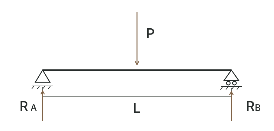
Vertical load and support reactions for one roller-support rod.
Loads, equations & text description
- Load sharing
- I assumed two rods share the wheel-supported vertical load Ww equally. One rod carries a central point load P = Ww/2 over span L.
- End reactions
- Equilibrium gives RA = RB = P/2 = Ww/4.
- Maximum bending moment
- For this central-load model, Mmax = PL/4 = Ww L/8. Forces are in N, span is in m, and bending moment is in N·m.
- Model scope
- This isolates vertical bending in one rod. Contact angles, traction, motor reactions, belt forces and frame-joint behavior require separate treatment.
04 / Iteration & testing
Hardware testing, revised analysis.
We physically tested the revised assembly after the frame and corner-bracing changes.
Next analysis iteration
My next step is to refine the ANSYS mesh and rerun the structural checks.
Team & vehicle context
University of Toronto Supermileage

University of Toronto Supermileage team and vehicle.
View full photograph
With the UTSM vehicle.
View full photographNext project / 02